| / We will do attentively.. | Collection / Supposes / E-mail / Site map |

|

| Industry News | |||||||
|
| Basic Technical Parameter |
HOW DOES IT WORK? |
||||||
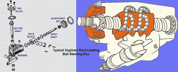
1956 - 1978 Non-Integral Saginaw-style Steering Box |
||||||
A basic working description of the Ford recirculating ball style steering box with attention to the critical adjustments and the common problem areas. The information below pertains specifically to an early Mustang/Falcon/Fairlane steering box, but other models are similar in operation. |
||||||
 |
||||||
Input Shaft/Worm Gear |
||||||
| The top end of the Input Shaft is splined, either to mount directly to the steering wheel, or to connect to a coupler from the steering wheel. The bottom end of the Input Shaft is machined into the shape of a Worm Gear. | ||||||
 |
||||||
SPLINED END WORM GEAR END |
||||||
On both ends of the Worm Gear section are areas where caged ball bearings ride. The shaft itself acts as the inner race for these ball bearings. There is an outer race for one of these ball bearings located inside the steering box Housing, and another race sets inside the Adjusting Nut. It is these two ball bearings that locate and hold the Input Shaft in place and the shaft rotates in them. |
||||||
|
||||||
Rack Block |
||||||
|
||||||
The Worm Gear goes inside the Rack Block and the individual ball bearings fill the grooves cut into both gears. The Rack Block has Ball Guides mounted on it that allow the balls to roll from one end to the other of the grooves cut into the Worm Gear and Rack Block. It is this recirculation of the ball bearings inside the Rack that gives the steering box it's recirculating-ball designation. |
||||||
|
||||||
As the Steering Shaft is turned, the Worm Gear is turned. The screw-action of the Worm Gear causes the Rack Block to move up and down the length of the Worm Gear. The recirculation ball action inside this setup acts to make the movement smooth and as friction-free as possible. |
||||||
SECTOR SHAFT |
||||||
The top end of the Sector Shaft has five vertical teeth machined on it. The bottom end is splined and threaded to hold the Pitman Arm in place and for the nut and washer that secure the Pitman Arm to the shaft. The steering box Housing has (in most cases) two needle bearings mounted inside it for the Sector Shaft to turn in. Some early 60's boxes use bronze bushings instead of needle bearings, but their function is the same. The Sector Shaft sets down in these needle bearings and serves as the inner race for them. The teeth on the top of the Sector Shaft mesh with the external teeth of the Rack Block. |
||||||
|
||||||
BASIC OPERATION |
||||||
| When you turn the steering wheel, you are also turning the Input Shaft and the Worm Gear. Due to the screw-like design of the Worm Gear, the Rack Block moves up and down on the Worm. The teeth on the outside of the Rack Block also move up and down in the box and push or pull on the teeth of the Sector Shaft, causing it to rotate. The rotation of the Sector Shaft causes the Pitman Arm to move left and right in the car, moving the steering linkage with it. This movement of the steering linkage causes the spindles to rotate on the ball joints and turn the wheels and tires. Simple. | ||||||
The design of the Worm Gear and Rack Block converts the twisting action of the steering wheel into a forward/rearward reciprocating action in the box. The design of the Rack Block and Sector Shaft converts the forward/rearward action into a side-to-side reciprocating action that can then move the steering linkage as it needs to. The use of the recirculation ball action makes the conversion smoother and easier that it could be done with gear teeth alone. |
||||||
CRITICAL ADJUSTMENTS |
||||||
There are only two adjustments when rebuilding a steering box; Input Shaft Bearing Load and Gear Mesh Load. |
||||||
Input Shaft Bearing Load |
||||||
The Input Shaft sets in two caged ball bearings and acts as the inner races of these bearings. The bottom bearing is mounted in the steering box Housing and is stationary. The top bearing is located in the Adjustment Nut and is therefore adjustable. Turning the Adjustment Nut in brings the two bearings closer together and clamps the Worm section of the Input Shaft between them. The tightness here must be enough to eliminate any play in the Input Shaft and keep it securely located in the Housing. However, the tightness must not be so great that the bearings bind or wear excessively. The proper tightness is determined by measuring the amount of drag it takes to turn the Input Shaft. This measurement must be taken without any additional drag from the other components in the box, so the Sector Shaft must be disconnected from the steering linkage and be removed or adjusted so far out as to reduce all drag with the teeth of the Rack Block. |
||||||
|
||||||
Gear Mesh Load |
||||||
| The teeth of the Rack Block and the teeth of the Sector Shaft mesh together. The space between the two center teeth on the Rack Block is machined slightly smaller than the other spaces and contacts the center tooth of the Sector Shaft more tightly. This design causes the the mesh of the teeth to tighten at the center of travel, which is where the steering box is when driving straight down the road. This center tightness is designed into the box so the box is tighter and the car has less tendancy to wander when going straight down the road - which is how the car is driven 99% of the time. | ||||||
The Gear Mesh is adjusted by turning the Adjustment Screw in or out of the Top Plate. Screwing the Adjustment Screw in pushes the Sector Shaft down into the box and forces the teeth to mesh with those of the Rack Block. Unscrewing the Adjustment Screw raises the Sector Shaft and unloads the teeth from each other. |
||||||
  |
||||||
| When properly adjusted, the mesh of the Rack Block teeth and Sector Shaft teeth add little or no additional drag to the turning of the Input Shaft, except at the center of travel. At center, the mesh should create an additional drag due to the designed interference of the gear teeth. Measurement of this additional drag at center is the Gear Mesh Load. This load must add a certain amount of additional load to the turning of the Input Shaft over the drag caused by the Bearing Load. This measurement must be taken with no additional load from the steering linkage or steering column. Too little Mesh Load and the box will not be tight at center and the car will wander the road when traveling in a straight line. Too much Gear Mesh and the teeth will bind, causing accelerated wear and, in some cases, breakage of the gear teeth and steering box failure. | ||||||
| Because the Gear Mesh Load is drag that is measured in addition to the Input Shaft Bearing Load, the only proper way of adjusting the steering box is to set the Input Shaft Bearing Load first before attempting to set the Gear Mesh Load. For directions and specifications for actually adjusting the Steering Box, go to the Steering Box Adjustment page. |
||||||
PROBLEM AREAS |
||||||
| Most problems in the steering box are caused by either excessive wear or corrosion. | ||||||
Excessive Wear |
||||||
As can be expected, the Input Shaft and Sector Shaft bearings eventually wear and loosen, causing excessive play in the gear mesh. Sometimes the caged ball bearings even disintegrate, spreading metal bits throughout the inside of the box. Replacement of the bearings with new pieces and re-setting the bearing and gear mesh adjustments will restore these areas to proper operating conditions. The main area to be concerned with is the wear of the teeth of the Rack Block and Sector Shaft where they mesh in the center of travel. The extra tightness that is designed into this area must be present for a rebuild to be possible. If the inside edges of the two center teeth on the Rack Block, and both tooth faces of the center tooth of the Sector Shaft, are so worn that they no longer produce a higher gear drag together, then one piece or both must be replaced to restore the original gear mesh settings. For pictures and more information on gear tooth wear, go to the Can I Rebuild My Own Steering Box? page. |
||||||
Corrosion |
||||||
Though it doesn't seem likely, it is fairly easy for water to get inside the steering box. It doesn't take much water to cause problems because once inside it never leaks out again. If the engine compartment is steam-cleaned or washed out, water can make its way into the box, usually through the area where the Input Shaft goes into the Housing. On steering boxes with long input shafts, there is no seal at all to prevent this, as you can look down where the shaft goes into the Adjustment Nut and actually see the upper Input Shaft ball bearings. If you find a steering box in a salvage yard that has been sitting in the open with no hood, you can bet that water has gotten inside the box. You would think that a box filled with grease could never rust, but you would be wrong. Water is a powerful solvent and will easily wash the heaviest grease off the internal parts of a steeing box and rust the parts away. Water will particularly settle between gear teeth or inside of the ball bearings. About a third of all steering box cores sent in for rebuilding have major internal pieces damaged beyond use due to corrosion. For pictures and more information on corrosion in the steering box, go to the Can I Rebuild My Own Steering Box? page. |

| Workshop | Products | Contact |
| Copyright © NINGBO CIE INDUSTRY AND TRADE CO.,LTD. All Rights Reserved. Design By HiSupplier Online Inc. |